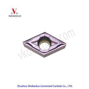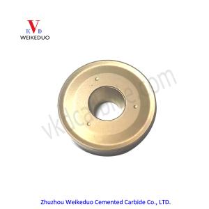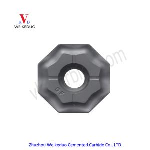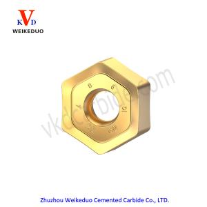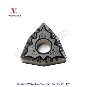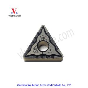
A chip breaking diagram for an insert geometry is defined by acceptable chip breaking for feed and depth of cut.
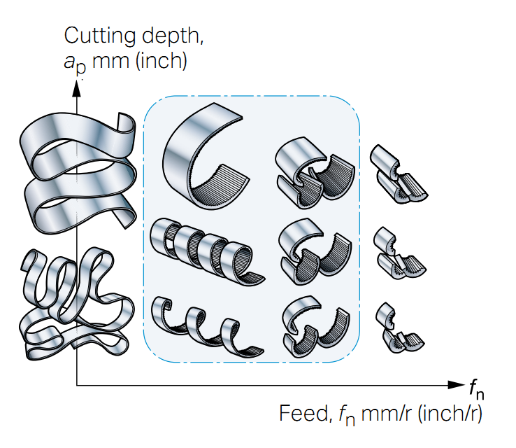
- Cutting depth (a,) and feed (fn) must be adapted to the chipbreaking area of the geometry to get acceptable chip control.
- Chip breaking which is too hard can lead to insert breakage.
- Chips which are too long can lead to disturbances in the machining process and bad surface finish.
Three main methods in Turning
R =Roughing
M =Medium machining
F = Finishing
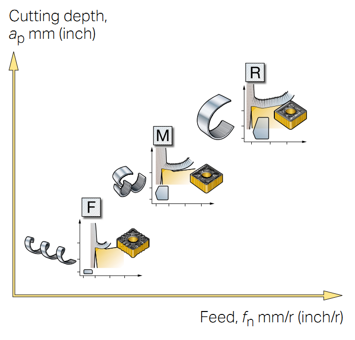
Roughing
- Maximum metal removal rate and/or severe conditions.
- Large cutting depth and feed rate combinations.
- High cutting forces.
Medium machining
- Most applications-general purpose.
- Medium operations to light roughing.
- Wide range of cutting depth and feed rate combinations.
Finishing
- Small cutting depths and low feed rates.
- Low cutting forces.


