Parting and grooving machining applications:
1)Height control of the parting and grooving cutting tool center.
- No matter what kind of parting and grooving cutting tool you will choose, only by ensuring that the insert is installed at 90 degrees from the center line of the workpiece can you obtain an ideal machining surface and reduce vibration during machining.
- The tolerance between the edge line of the insert and the center of the workpiece should be +-0.1mm, especially for the parting of the lever and the grooving of the workpieces with small diameters, which can improve the tool life and reduce the resistance and the burr.
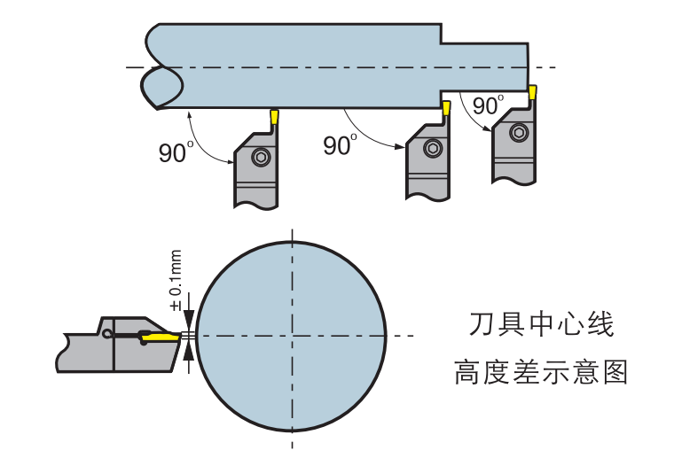
2)Parting
- When the insert is approaching to the center of the workpiece, the feed rate should be reduced by 30%, which is beneficial to improve the tool life and surface quality.
- If allowed, reduce the overhang as much as possible to ensure good stability.
3)External grooving, turning and profileturning
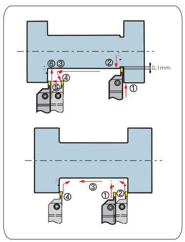
- The pass sequence:
When the cutting depth>0.5mm, the radialentries (maximum depth of cut can reach 0.75* insert widths)—the radial exists(about 0.1mm), and the axial feed—the required depth of the radial machining cutting tool.
When cutting the bottom diameter or chamfering (finishing), the pass sequence shown in the picture can be used to reduce the vibration caused by the friction between the tool and the chip.
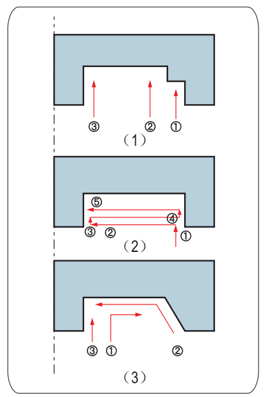
Face grooving and turning
Finishing (multi-slot cutting) cuts inward from the largest diameter, and the insert is slightly offset to the inner edge when exist. As shown in the figure(1).
Groove turning
The axial turning depth doesn’t exceed 0.75*S (the width of the insert edge),and the groove width is greater than the groove depth, When The groove depth is greater than the groove width as shown in the figure(2), the multi-slot cutting is recommended.
Finishing
Finish the bottom and the edge of the outer diameter at first, and then finish the inner diameter to the required size, as shown in the picture(3).
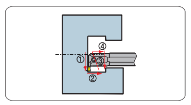
Inner hole grooving andturning
The pass sequence shown in the figure is for better evacuation of the chips, and the feed always starts from the direction away from the end face of the hole.


